Tutorial 4 - Transient Solves
The files for this tutorial can be found in “examples/tutorial_4”.
Governing Equations
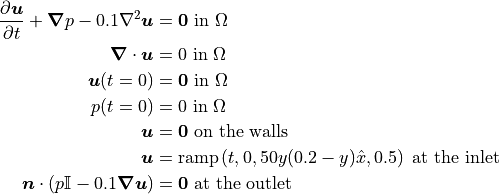
This tutorial will demonstrate how to solve the transient Stokes equations. The governing equations are similar to those used in Tutorial 4 - Transient Solves. However, instead of a steady-state solve the inlet boundary condition is ramped up from zero velocity and pressure and the domain is allowed to reach steady-state.

Note that the inlet boundary condition ramps from zero to the steady-state boundary condition in 0.5s following a cosine profile.
At steady-state, the exact solution is as follows:

The Main Configuration File
A new section must be added to the main configuration file to specify the parameters for the transient solve. In this tutorial, the first-order implicit Euler scheme will be used for time discretization. For a full list of the available time discretization schemes see Configuration File Options Guide. Using a time range of 0s to 2s will give the simulation sufficient time to reach steady-state and a time step of 0.005s is chosen for reasonable accuracy.
[TRANSIENT]
transient = True
scheme = implicit euler
time_range = 0, 2
dt = 0.005
In addition to an error analysis of the final steady-state results, results will be saved to file throughout the duration of the simulation for later visualization. This requires a new parameter - “save_frequency” - to specify how often results should be saved. In this case, results will be saved every 0.1s. “save_frequency” can also be specified as “x, numit” if results should be saved after every x time steps.
[VISUALiZATION]
save_to_file = True
save_type = .vtu
save_frequency = 0.1, time
The Boundary Condition Configuration File
The boundary condition are similar to those used in Tutorial 4 - Transient Solves with the exception of the inlet Dirichlet boundary condition which now ramps from zero to its steady-state value in 0.5s.
[DIRICHLET]
u = inlet -> [ramp(t, 0.0, 50*y*(0.2 - y), 0.5), 0.0]
    wall  -> [0.0, 0.0]

[STRESS]
stress = outlet -> [0.0, 0.0]
The Initial Condition Configuration File
Since this is a transient simulation an initial condition is needed. Initial conditions must be specified for all model variables. They can be constructed to take different values on different marked regions of the domain. However, generally they will take the same value over the entire domain, which is indicated by the “all” parameter. In this tutorial, both the velocity and pressure fields will be initialized to zero.
[STOKES]
u = all -> [0.0, 0.0]
p = all -> 0.0
Running the Simulation
The simulation can be run from the command line; within the directory examples/tutorial_4/ execute python3 -m opencmp config.
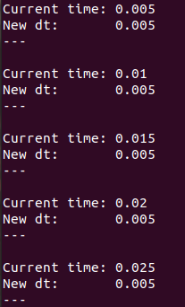
This simulation will take longer to run than the previous tutorials. Its progress can be tracked by print outs of the current time and time step value at each time step.

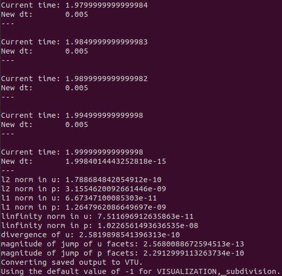
Once the simulation has finished the values of the error metrics will also be printed out.

The results match the known exact solution well, the incompressibility constraint is well satisfied, and the final velocity and pressure fields are more-or-less continuous as expected.